Dimensional Tolerances for Cut C-Cores, Cut E-Cores & Toroids
C-Cores

- Custom sizes
- Custom shapes
- Multiple Cuts
- Special air gap cuts
- Tighter tolerances
- Low noise applications
- Diamond-lapped mating surfaces
- Special edge chamfering
- Special high temperature heat stabilization processes
- Epoxy coating
- Special edge chamfering
- Epoxy coating
- Special stack resistance requirements
- Special part marking
- Custom assemblies
- Custom grinding & machining
- Small Planar-type geometries
- Call for more details about these other possibilities
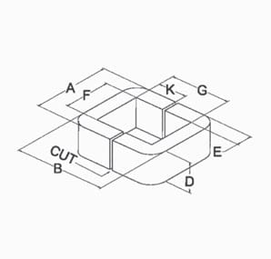
Dimensional Tolerances for Cut C-Cores per EIA Standard RS-217
Core Dimension | Material Thickness (inches) | Allowable Tolerances (inches) |
A = Outside Core Width | All | +0.031 max when A ≤ 1.500
+0.047 max when 1.500 < A ≤ 2.500 +0.062 max when 2.500 < A ≤ 3.500 +0.094 max when A > 3.500 |
B = Outside Core Height | 0.0005, 0.001, 0.002 | +0.062 max when B ≤ 2.000
+0.188 max when 2.000 < B ≤ 4.000 +0.375 max when B > 4.00 |
0.004 through 0.014 | +0.062 max when B < 3.000
+0.156 max when 3.000 ≤ B ≤ 4.000 +0.188 max when 4.000 < B ≤ 6.000 +0.375 max when 6.000 < B ≤ 12.000 +0.438 max when B > 12.000 |
|
D = Core Strip Width | All * | +0.031, -0 when D ≤ 1.000
+0.047, -0 when 1.000 < D ≤ 2.812 +0.062, -0 when D > 2.812 +0.094, -0 when E > 2.500 |
E = Core Leg Buildup | 0.0005 through 0.004 | ±0.016 when E ≤ 0.250
+0.031, -0.016 when 0.250 < E ≤ 1.000 ±0.031 when E > 1.000 |
0.007 through 0.014 | ±0.016 when E < 0.250
+0.031, -0.016 when 0.250 ≤ E < 0.562 ±0.031 when E ≥ 0.562 |
|
F = Inside Window Width | All | -0.016 minimum |
G = Inside Window Height | All | -0.016 minimum |
K = Cut Dimension | All | G÷2 if G < 3.750, ± 0.062
1.687 if G ≥ 3.750, ±0.062 |
R = Inside Window Corner Radius (Reference Only) | 0.0005 through 0.004
0.007 through 0.014 All All |
0.031 when F & G ≤ 2.000
0.062 when F & G ≤ 2.000 0.125 when F or G > 2.000 and F & G ≤ 5.000 0.156 when F > 5.000 |
Maximum Core Tilt | All | 0.031 when B < 3.500
0.062 when B ≥ 3.500 |
A & B dimensions are held to a maximum tolerance only, negative tolerances are controlled by the F, G, & E dimensions. F & G dimensions are held to a minimum tolerance only, positive tolerances are controlled by the A, B & E dimensions.
* Nanocrystalline tolerance on the D dimension is ± the stated positive tolerance to accommodate material shrinkage during the annealing process. Other tolerances may be different depending on core geometry. Contact our engineering department for more details. |
- MK Magnetics will gladly manufacture cores to your specific dimensional and physical requirements such as: non-standard mechanical tolerances, multiple cuts, or diamond lapped for lowest possible excitation and/or acoustical noise.
E-Cores

- Custom sizes
- Custom shapes
- Multiple Cuts
- Special air gap cuts
- Tighter tolerances
- Low noise applications
- Diamond-lapped mating surfaces
- Special edge chamfering
- Special high temperature heat stabilization processes
- Epoxy coating
- Special edge chamfering
- Epoxy coating
- Special stack resistance requirements
- Special part marking
- Custom assemblies
- Custom grinding & machining
- Small Planar-type geometries
- Call for more details about these other possibilities
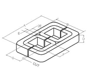
Dimensional Tolerances for Cut E-Cores
Core Dimension | Material Thickness (inches) | Allowable Tolerances (inches) |
A = Outside Core Width | 0.001 through 0.004 | +0.094 max when A ≤ 5.000
+0.188 max when 5.000 < A ≤ 10.000 +0.312 max when A > 10.000 |
0.007 through 0.014 | +0.125 max when A ≤ 5.000
+0.250 max when 5.000 < A ≤ 10.000 +0.375 max when A > 10.000 |
|
B = Outside Core Height | 0.001, 0.002, 0.004 | +0.094 max when B ≤ 5.000
+0.156 max when 5.000 < B ≤ 10.000 +0.250 max when B > 10.000 |
0.007 through 0.014 | +0.125 max when B ≤ 5.000
+0.188 max when 5.000 < B ≤ 10.000 +0.312 max when B > 10.000 |
|
D = Core Strip Width | All * | +0.031, -0 when D < 1.000
+0.047, -0 when 1.000 ≤ D < 2.000 +0.062, -0 when D ≥ 2.000 +0.156, -0 when 2E > 2.000 |
2E = Core Leg Buildup | All | ±0.031 when 2E ≤ 1.000
+0.062, -0.031 when 1.000 < 2E ≤ 2.000 ±0.062 when 2E > 2.000 |
F = Inside Window Width | All | -0.016 minimum |
G = Inside Window Height | All | -0.016 minimum |
K = Cut Dimension | All | G ÷ 2.000, ± 0.062 |
R = Inside Window Corner Radius (Reference Only) | 0.0005 through 0.004
0.007 through 0.014 All All |
0.031 when F & G ≤ 2.000
0.062 when F & G ≤ 2.000 0.125 when F or G > 2.000 and F & G ≤ 5.000 0.156 when F > 5.000 |
Maximum Tilt | All | 0.031 when F < 2.500
0.062 when F ≥ 2.500 |
A&B dimensions are held to a maximum tolerance only, negative tolerances are controlled by the F, G, & 2E dimensions. F&G dimensions are held to a minimum tolerance only, positive tolerances are controlled by the A, B & 2E dimensions.
* Nanocrystalline tolerance on the D dimension is ± the stated positive tolerance to accommodate material shrinkage during the annealing process. Other tolerances may be different depending on core geometry. Contact our engineering department for more details. |
Toroids

- Customizable to meet your needs
- Cut in half
- Diamond lapped if cut in half
- Epoxy coated
- Matched sets
- Gapped to meet your inductance requirements
- Air gapped for Hall sensors
- Chamfered or radiused ID & OD
- Special stack resistance requirements
- Nylon & Aluminum cased
- Multiple Cuts
- Call for more details about these and other possibilities
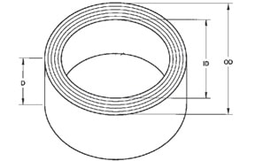
Dimensional Tolerances for Toroids
Core Dimension | Material Thickness (inches) | Allowable Tolerances (inches) |
OD = Outside Core Width or Diameter | All | +0.031, -0.016 when OD ≤ 1.500
±0.031 when 1.500 < OD ≤ 2.500 +0.062, -0.031 when 2.500 < OD ≤ 3.500 ±0.062 when 3.500 < OD ≤ 12.000 +0.125, -0.062 when 12.000 < OD ≤ 24.000 ±0.125 when OD > 24.000 |
ID = Inside Core Width or Diameter | All | ±0.016 when ID ≤ 2.500
+0.031, -0.016 when 2.500 < ID ≤ 3.500 ±0.031 when 3.500 < ID ≤ 12.000 +0.062, -0.031 when 12.000 < ID ≤ 24.000 ±0.062 when ID > 24.000 |
D = Core Strip Width | All * | +0.031, -0 when D ≤ 1.000
+0.047, -0 when 1.000 < D ≤ 2.812 +0.062, -0 when D > 2.812 |
E = Core Buildup | All | ±0.016 when E ≤ 0.250
+0.031, -0.016 when 0.250 < E ≤ 1.000 ±0.031 when E > 1.000 |
For unimpregnated cores, measurements will be made with core shaped into the most favorable position because these cores are often flexible.
|