Dimensional Tolerances for Cut C-Cores, Cut E-Cores & Toroids

There are many magnetic cores available, each of which is designed and built to distinct specifications to suit different applications. If you are a design engineer or purchasing agent for a manufacturing company, it is important you choose the right magnetic core solution for the intended application. Otherwise, it may not work as intended in the manufactured assembly. 

One of the key factors to keep in mind during the core selection process are the dimensional tolerances. Dimensional tolerance refers to the permissible range of dimensions for a particular type of magnetic core. While these values may vary depending on the core’s shape, material type, and material thickness, they indicate the minimum and maximum size it can be to remain compliant with the manufacturing project’s requirements and restrictions. If any dimension falls outside of this range, the core is not compliant and not suitable for use in the particular manufacturing project. Some magnetic component applications are so sensitive that even a variance of less than .003 inches cannot be tolerated. 

Looking for a supplier you can trust to deliver magnetic cores that meet your dimensional tolerance demands? Turn to the experts at MK Magnetics! We can design and manufacture components that will accommodate nearly any pre-fab coil and fit into some of the tightest spaces. Whether you need industry-standard or tighter tolerances, we have what it takes to provide a core solution that fits optimally within your device. Below, we highlight our magnetic core offerings.

C-Cores

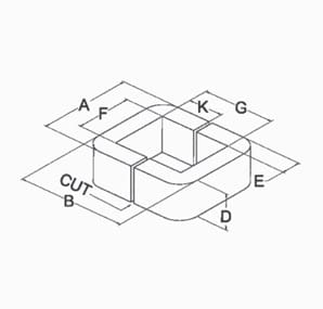
C-Core Dimensional Diagram

C-cores are manufactured by first winding the electrical steel strip on a mandrel and then cutting the resin-bound core. This allows windings to be placed on either or both core legs.

These magnetic cores have a number of advantages over other types of cores. For example, their wound core form is better suited for magnetic induction current operations, while their material grain structure offers better efficiency than other core shapes. Some of the other benefits they offer include decreased energy costs (due to lower specific iron watt losses), reduced copper winding material requirements (due to smaller core dimensions and lighter core weights), lowered labor costs (due to easier assembly requirements), and quieter operations. 

See the table below for our dimensional tolerance capabilities for these cores.

Dimensional Tolerances for Cut C-Cores per EIA Standard RS-217

Core Dimension Material Thickness (inches) Allowable Tolerances (inches)
A = Outside Core Width All +0.031 max when A ≤ 1.500
+0.047 max when 1.500 < A ≤ 2.500
+0.062 max when 2.500 < A ≤ 3.500
+0.094 max when A > 3.500
B = Outside Core Height 0.0005, 0.001, 0.002 +0.062 max when B ≤ 2.000
+0.188 max when 2.000 < B ≤ 4.000
+0.375 max when B > 4.00
0.004 through 0.014 +0.062 max when B < 3.000
+0.156 max when 3.000 ≤ B ≤ 4.000
+0.188 max when 4.000 < B ≤ 6.000
+0.375 max when 6.000 < B ≤ 12.000
+0.438 max when B > 12.000
D = Core Strip Width All * +0.031, -0 when D ≤ 1.000
+0.047, -0 when 1.000 < D ≤ 2.812
+0.062, -0 when D > 2.812
+0.094, -0 when E > 2.500
E = Core Leg Buildup 0.0005 through 0.004 ±0.016 when E ≤ 0.250
+0.031, -0.016 when 0.250 < E ≤ 1.000
±0.031 when E > 1.000
0.007 through 0.014 ±0.016 when E < 0.250
+0.031, -0.016 when 0.250 ≤ E < 0.562
±0.031 when E ≥ 0.562
F = Inside Window Width All -0.016 minimum
G = Inside Window Height All -0.016 minimum
K = Cut Dimension All G÷2 if G < 3.750, ± 0.062
1.687 if G ≥ 3.750, ±0.062
R = Inside Window Corner Radius (Reference Only) 0.0005 through 0.004
0.007 through 0.014 All
All
0.031 when F & G ≤ 2.000
0.062 when F & G ≤ 2.000
0.125 when F or G > 2.000 and F & G ≤ 5.000
0.156 when F > 5.000
Maximum Core Tilt All 0.031 when B < 3.500
0.062 when B ≥ 3.500
A & B dimensions are held to a maximum tolerance only, negative tolerances are controlled by the F, G, & E dimensions. F & G dimensions are held to a minimum tolerance only, positive tolerances are controlled by the A, B & E dimensions.
* Nanocrystalline tolerance on the D dimension is ± the stated positive tolerance to accommodate material shrinkage during the annealing process. Other tolerances may be different depending on core geometry. Contact our engineering department for more details.
  • MK Magnetics will gladly manufacture cores to your specific dimensional and physical requirements such as: non-standard mechanical tolerances, multiple cuts, or diamond lapped for lowest possible excitation and/or acoustical noise.

E-Cores

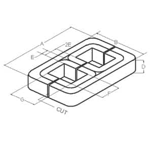
E-Core Dimensional Diagram

E-cores offer a good solution for some magnetic systems. Shell-type configurations have a three-leg design that generally consists of a center leg with twice the area of either outer leg. Three-phase transformer E-cores have three equally sized legs that are wound around the mandrel, similar to the C-core.

These magnetic cores can be made from different types and grades of materials to suit different applications. Additionally, similar to C-cores, they can decrease energy costs, reduce copper winding material requirements, and lower labor costs when properly designed and constructed. They are commonly used in transformers, inductors, transducers, chokes, and suppressors.

See the table below for our dimensional tolerance capabilities for these cores.

Dimensional Tolerances for Cut E-Cores

Core Dimension Material Thickness (inches) Allowable Tolerances (inches)
A = Outside Core Width 0.001 through 0.004 +0.094 max when A ≤ 5.000
+0.188 max when 5.000 < A ≤ 10.000
+0.312 max when A > 10.000
0.007 through 0.014 +0.125 max when A ≤ 5.000
+0.250 max when 5.000 < A ≤ 10.000
+0.375 max when A > 10.000
B = Outside Core Height 0.001, 0.002, 0.004 +0.094 max when B ≤ 5.000
+0.156 max when 5.000 < B ≤ 10.000
+0.250 max when B > 10.000
0.007 through 0.014 +0.125 max when B ≤ 5.000
+0.188 max when 5.000 < B ≤ 10.000
+0.312 max when B > 10.000
D = Core Strip Width All * +0.031, -0 when D < 1.000
+0.047, -0 when 1.000 ≤ D < 2.000
+0.062, -0 when D ≥ 2.000
+0.156, -0 when 2E > 2.000
2E = Core Leg Buildup All ±0.031 when 2E ≤ 1.000
+0.062, -0.031 when 1.000 < 2E ≤ 2.000
±0.062 when 2E > 2.000
F = Inside Window Width All -0.016 minimum
G = Inside Window Height All -0.016 minimum
K = Cut Dimension All G ÷ 2.000, ± 0.062
R = Inside Window Corner Radius (Reference Only) 0.0005 through 0.004
0.007 through 0.014 All
All
0.031 when F & G ≤ 2.000
0.062 when F & G ≤ 2.000
0.125 when F or G > 2.000 and F & G ≤ 5.000
0.156 when F > 5.000
Maximum Tilt All 0.031 when F < 3.500
0.062 when F ≥ 3.500
A&B dimensions are held to a maximum tolerance only, negative tolerances are controlled by the F, G, & 2E dimensions. F&G dimensions are held to a minimum tolerance only, positive tolerances are controlled by the A, B & 2E dimensions.
* Nanocrystalline tolerance on the D dimension is ± the stated positive tolerance to accommodate material shrinkage during the annealing process. Other tolerances may be different depending on core geometry.
Contact our engineering department for more details.

Toroids

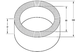
Toroid Dimensional Diagram

Toroid cores are donut-shaped. In a magnetic assembly, the magnet wire coil winds through the hole and around the perimeter of the toroid. Ideally, it should be distributed evenly around the circumference as the symmetry will generate a magnetic field of circular loops that are constrained to the inside of the core. This design increases the efficiency of the transformer while decreasing electromagnetic interference (EMI). 

There are many benefits to using toroid cores. For example, they can be manufactured with chamfered inside and outside edges, which allow the coil to be wound without the use of a protective capping strip or the risk of the banding or winding breaking. Other advantages include smaller footprint and greater core utilization. 

See the table below for our dimensional tolerance capabilities for these cores.

Dimensional Tolerances for Toroids

Core Dimension Material Thickness (inches) Allowable Tolerances (inches)
OD = Outside Core Width or Diameter All +0.031, -0.016 when OD ≤ 1.500
±0.031 when 1.500 < OD ≤ 2.500
+0.062, -0.031 when 2.500 < OD ≤ 3.500
±0.062 when 3.500 < OD ≤ 12.000
+0.125, -0.062 when 12.000 < OD ≤ 24.000
±0.125 when OD > 24.000
ID = Inside Core Width or Diameter All ±0.016 when ID ≤ 2.500
+0.031, -0.016 when 2.500 < ID ≤ 3.500
±0.031 when 3.500 < ID ≤ 12.000
+0.062, -0.031 when 12.000 < ID ≤ 24.000
±0.062 when ID > 24.000
D = Core Strip Width All * +0.031, -0 when D ≤ 1.000
+0.047, -0 when 1.000 < D ≤ 2.812
+0.062, -0 when D > 2.812
E = Core Buildup All ±0.016 when E ≤ 0.250
+0.031, -0.016 when 0.250 < E ≤ 1.000
±0.031 when E > 1.000
For unimpregnated cores, measurements will be made with core shaped into the most favorable position because these cores are often flexible.
For epoxy coated (cased or encapsulated) cores add .0.040″ to the maximum “OD” and “D” dimensions, subtract 0.040″ from the minimum “ID” dimension. “E” dimension tolerance applies before coating only.
* Nanocrystalline tolerance on the D dimension is ± the stated positive tolerance to accommodate material shrinkage during the annealing process. Other tolerances may be different depending on core geometry.
Contact our engineering department for more details.

MK Magnetics: Your Expert and Partner for Magnetic Core Needs

At MK Magnetics, we can manufacture magnetic cores to your exact specifications. If you want more information on dimensional tolerances for our cut C-cores, cut E-cores, and toroid cores, contact us today. If you’re ready to make an order, request a quote.